

Table of Contents
- What You'll Need Before You Start
- Safety First: Battery Disconnection and Precautions
- Accessing the Light Assembly and Identifying Wiring
- LED Load Resistor Installation to Stop Hyper-Flash
- Preventing Hyper-Flash on LED Indicators: Wiring the Sequential Module
- Automotive Lighting ADR Compliance: What You Must Check
- Testing, Weatherproofing and Troubleshooting Sequential Signal Light Installations
- Frequently Asked Questions
Last Updated: September 16, 2026
What You'll Need Before You Start
Sequential signal light installation tips start with preparation, not wiring. A sequential signal light is an indicator assembly that illuminates its LEDs in a sweeping sequence rather than all at once, and fitting one reliably comes down to having the right parts on the bench before you touch the car.
Gather everything first, because a second trip to the parts store mid-install is how wires get crossed.
What you'll need:
- Sequential module matched to your vehicle's indicator circuit
- LED load resistors (one per indicator side, if required)
- Wiring harness adapters for your model
- Trim removal tools
- Multimeter
- Crimp connectors, splice connectors and heat shrink tubing
- Dielectric grease
- Electrical tape and cable ties
- Soldering iron (optional, but preferred for permanent joins)
Safety First: Battery Disconnection and Precautions
Disconnect the negative battery terminal before touching any lighting circuit. This is the single non-negotiable step. Indicator circuits sit on a 12V system, and while 12V rarely injures, a short across a live circuit can melt insulation, blow fuses, or damage the body control module.
Wait a few minutes after disconnection before working near airbag sensors or CANbus wiring. Modern vehicles keep modules awake briefly after shutdown.
- Disconnect negative terminal first, reconnect it last
- Never work on a circuit you haven't confirmed is dead with a multimeter
- Keep the battery disconnected for the entire install, not just the removal phase
- If your vehicle has a factory alarm or memory settings, note them before disconnecting
A common mistake is reconnecting the battery mid-install to "check something." That's how shorts happen. Finish the wiring, then reconnect.
Accessing the Light Assembly and Identifying Wiring
Access the light assembly through the engine bay or by removing the taillight housing from inside the boot or rear quarter panel, depending on your model. Most housings are held by two to four bolts or clips behind trim panels.
Use trim removal tools, not a flathead screwdriver. Plastic clips crack easily and replacements are annoying to source.
Once the housing is out, identify three wires on the factory harness:
- Ground, usually black or brown
- ACC power, live when the ignition is on
- Turn signal feed, pulses when the indicator activates
The turn signal feed is the one you'll splice into for the sequential module. Confirm each wire with a multimeter rather than trusting colour codes; manufacturers change them between model years. A continuity test on the ground wire and a voltage check on the ACC line takes two minutes and prevents hours of diagnosis later.
LED Load Resistor Installation to Stop Hyper-Flash
Hyper-flash happens because LEDs draw far less current than the halogen bulbs the vehicle's flash relay expects. The relay reads the low current draw as a blown bulb and speeds up the flash rate as a warning. A load resistor fixes this by adding resistance back into the circuit so the relay sees a normal load.
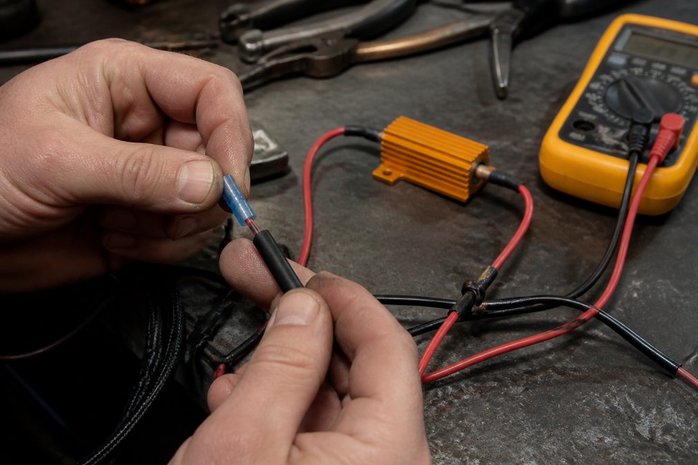
Choosing the right resistor
Most 12V indicator circuits originally ran a 21W incandescent globe. To mimic that load with an LED, you need a resistor that dissipates roughly the same power. The common spec is a 6 ohm, 50W ceramic resistor per indicator side. A 6 ohm resistor across a 12V circuit draws about 2A, which is close enough to a 21W globe for the relay to read as normal. Some vehicles with a lower-wattage factory globe (such as 5W or 16W) may need a higher resistance value, so check the factory globe rating before buying.
Do not use a low-wattage resistor. A 25W resistor will overheat and fail, and a resistor rated below the circuit's actual dissipation will cook itself and anything near it.
Wiring the resistor
Install one resistor per indicator side, wired in parallel across the LED signal and ground wires:
- Identify the signal and ground wires at the indicator connector
- Strip 10mm of insulation from both
- Crimp or solder the resistor leads to each wire
- Seal the join with heat shrink
- Mount the resistor to metal bodywork, away from plastic and wiring
Resistors get hot in use, a 50W ceramic resistor can reach temperatures that soften plastic trim and degrade nearby insulation. Mounting them against plastic is a common mistake that ends in melted panels. Bolt the resistor body to a metal panel or bracket with a small self-tapping screw or a dedicated resistor mounting clip, and keep at least 25mm of clearance from any wiring loom or plastic.
When a resistor is not the right fix
Some vehicles manage hyper-flash through coding changes rather than resistors. If your model supports it, a workshop with diagnostic software can recode the body control module to accept LED loads, which avoids the heat and wiring of a resistor entirely. This is common on many European platforms.
On CANbus-monitored vehicles, a standard load resistor may not clear the dashboard warning even when the flash rate is correct. The module is looking for a specific current signature, not just a resistance value. In that case you need a CANbus-rated resistor kit or a sequential module with built-in CANbus emulation. Fitting a plain resistor to a CANbus car often leaves the bulb error on the dash while the lights work perfectly, a confusing result that sends many installers back to the parts store.
Preventing Hyper-Flash on LED Indicators: Wiring the Sequential Module
Preventing hyper-flash on LED indicators comes down to matching the module to your vehicle's electrical architecture. Wire the sequential module inline between the factory turn signal feed and the LED assembly, following the pinout diagram supplied with the module.
- Power in, from the ACC or turn signal feed
- Ground, to chassis or factory ground
- Signal out, to the LED indicator assembly
Where to mount the module
The module itself is small and light, but it needs to live somewhere dry and accessible. The two practical options are inside the light housing (if there is room and the housing is sealed) or behind the trim panel near the indicator. Inside the housing keeps the wiring short and tidy, but it makes future access harder and exposes the module to any moisture that gets into the housing.
Making the joins durable
Reversibility: keeping the factory harness intact
Automotive Lighting ADR Compliance: What You Must Check
Before you finalise the install, confirm:
- Indicator colour is amber, as required
- Flash rate falls within the legal range (not hyper-flashing)
- No white light shows from the indicator position when not signalling
- Sequential sweep doesn't obscure the indicator's visibility to other drivers
Testing, Weatherproofing and Troubleshooting Sequential Signal Light Installations
Troubleshooting common faults:
| Symptom | Likely Cause | Fix |
|---|---|---|
| Hyper-flash | Missing or faulty load resistor | Fit resistor, check resistance value |
| No sequence, solid flash | Module wired to wrong feed | Confirm signal wire with multimeter |
| Intermittent flicker | Poor splice or voltage drop | Re-solder join, seal with heat shrink |
| Dashboard bulb error | CANbus monitoring active | Fit CANbus-rated resistor or module |
| Sequence runs backwards | Signal and ground reversed | Swap connections at module |
Frequently Asked Questions
Do I need a load resistor for sequential LED turn signals?
Most vehicles need one. Factory flasher relays expect the current draw of a halogen globe, and LEDs pull far less, which triggers hyper-flash. A load resistor wired in parallel across the indicator circuit restores that draw and settles the flash rate. Some vehicles have a compatible flasher relay or a setting you can change instead, so check your model before buying resistors. If you fit a resistor, mount it on metal, not plastic, because it gets hot during use.
Are sequential turn signals legal for road use?
Sequential indicators can be legal if they meet the Australian Design Rules for your vehicle category. The key requirements are flash rate, colour, visibility angle and that the lamp still functions as a proper indicator. A sweeping pattern that completes within the normal flash cycle is generally accepted, but a pattern that is too slow or dims the lamp below the required output is not. Check the ADR that applies to your vehicle and confirm compliance before installing.
How do I prevent hyper-flashing after installing sequential lights?
Preventing hyper-flash on LED indicators comes down to matching the current draw the flasher relay expects. Fit a load resistor in parallel on each indicator circuit, or swap to an LED-compatible flasher relay if your vehicle supports one. Use crimp connectors and heat shrink rather than twisting wires, and test each side separately before reassembling the housing. If hyper-flash persists, check for a poor ground connection, which is a common cause of erratic flash rates.
Can I install sequential signals on any vehicle model?
Not every model, but most are workable. The deciding factors are whether the housing has room for the module and resistor, whether the wiring can be accessed without cutting factory looms, and whether the vehicle uses CANbus monitoring that flags globe-out errors. Vehicles with simple switched indicator circuits are the easiest. Models with complex body control modules may need additional error-cancelling hardware. Check compatibility for your specific make and model before ordering.